Table of Contents
/* Imported from Wayback Machine
 Original URL : https://retrobrewcomputers.org/doku.php?id=boards:ecb:bus-monitor:start
 Snapshot date: 2025-11-17
 Generator    : wayback-archiver
*/
ECB Bus Monitor


Introduction
The ECB bus monitor is a debugging/prototyping card which allows a builder to monitor the state of the ECB bus. The ECB bus reflects the state of the the SBC or processor card plugged into the bus so it is helpful to understand the proper operation of the computer system.
ECB bus monitor features:
Displays state of ECB bus address lines [A0-A15], data lines [D0-D7], and control lines using LEDs
Allows the builder to single step through instructions
Allows the builder to set “trap” address to halt the SBC processor when a specific address is reached
Allows the builder to set conditional trapping combinations including on memory and I/O requests
Note: Newer RBC processor cards have extended the address and data lines beyond what this card can display. It is most useful with the Z80-based SBC/processor cards.
This board was derived from information in an article published in the “c't Projekt” section of c't magazine in Germany. The original article can be found here.
Hardware Documentation
Current Version: “003”
Board: ecb_busmonitor-full-brd.pdf
Schematic: ecb_bus_monitor_schematic.pdf
Manufacturing Files:  ]] Gerber files were not on old wiki. ]]
KiCAD Files: ecb_busmonitor-003.zip
For information on early prototype boards, see the historical page.
Build Information
Parts List
LED Labels
Default Positions of Switches
From: Don Caprio <ilvu…@gmail.com>
Date: Sat, 02 Apr 2011 16:22:25 -0700
Local: Sat, Apr 2 2011 7:22 pm
Subject: Re: [N8VEM: 9121] Re: ECB Bus Monitor
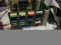
Hey, I got my bus monitor working. That is lights blink, status and data LED's are responsive. Address LED's flicker during boot and running CP/M commands.
This was totally a high tech approach :) I looked at the home page of the N8VEM. You see a picture of the bus monitor. If you look very closely you can pretty much tell what the position of the switches are. I set mine as pictured and it now it works. I still would like to know what the switches are and what functions they provide.
Set all address switches to ON (SW_1_2 & SW_3_4).
On the remaining two dip switches set them all to OFF. Turn switch position 5 ON (SW2) Turn switch position 4 and 5 ON (SW1)
Notes on Operation
For what it's worth, what I've been able to decode from the schematic is as follows:
SW_HEX_1_2 and SW_HEX_3_4 are “match” switches. Each set of 4 switches is used to specify a single hex number which is matched against A0..A16. For each nybble that matches, LEDs 3,4,5, and 6 on the STATUS LED display will light. This is a tremendous debugging aid (see the paragraph below on SW2 for how to use this). I guess the result could be inverted and used to gate the clock to the Z80 or something like that… (which would only work with a CMOS Z80, not a “standard” CPU!)
SW1 4&5 allow RD and MREQ to generate a signal that is used to update the displays. You can use SW1 to select any of WR, MREQ, RD, RFSH,IORQ, and/or M1 (switches 3..8 respectively) to enable the latches - which l guess is a great little debugging aid - you can check the bus only on writes, reads, or memory or I/O transactions, etc - the rest of the display will stay “static” until one of these signals is true.
SW2-5 enables the output of SW1 to be used as a source for the latching clock. Other sources are the address match signals, enabled on SW2-1 (H4 nybble)..SW2-4 (H1 nybble). One or all of these triggers can be used to “freeze” the display at that matching address. This allows you to write some test code that accesses a specific memory or I/O address, and when you set H4…H1 to that address, when the CPU acccesses the code, the displays will freeze in place. So you know it works. How cool is that?
There are some other refinements (SW1-1 for example) that naybe only a German speaker will be able to figure out… Or the designer of the bus monitor board itself?
I hope this helps! PCP
Videos Demonstrating Operation
See the ECB Bus Monitors Videos page for a set of videos showing the operation of this board.
Photo Gallery


File List
Filename
Filesize Last modified bus_monitor_parts_list_clean.pdf 42.9 KiB 2015/11/03 01:17 bus_monitor_parts_list_clean.xls 26.5 KiB 2015/11/03 01:17 busmonitor_ger.zip 9.5 KiB 2015/11/03 01:13 ecb_bus_6_english.txt 17.8 KiB 2015/11/03 01:09 ecb_bus_6_german.txt 22.3 KiB 2015/11/03 01:13 ecb_bus_monitor_default_switch_settings.txt 856.0 B 2015/11/03 01:09 ecb_bus_monitor_layout.pdf 737.9 KiB 2015/11/03 01:09 ecb_bus_monitor_schematic.pdf 127.8 KiB 2015/11/03 01:09 ecb_busmonitor-003.zip 167.5 KiB 2015/11/03 01:09 ecb_busmonitor-full-brd.pdf 649.0 KiB 2015/11/03 01:09 ecb_ct_bus_monitor.pdf 29.5 MiB 2015/11/03 01:09 ecb_led_labels.xls 33.5 KiB 2015/11/03 01:09